Facilities
In addition to the other GALCIT experimental facilities and small-scale experimental facilities that serve small, special-purpose experimental efforts, our group relies on a host of larger-scale general-purpose flow facilities designed and particularly-well suited for the study of turbulence and turbulent mixing.
- Supersonic Shear Layer (S3L) facility: This is designed for the study of
turbulent shear-layer mixing and contact-surface instabilities at high Reynolds number,
from incompressible- to supersonic-flow conditions. It permits the quantitative study of
molecular mixing and mixing-rate phenomena through the use of variable kinetic-rate chemical
reactions of such reactants as hydrogen and fluorine.
- Variable Pressure Flow (VPF) facility: Originally built to study Reynolds-number
effects in turbulent-jet mixing, it operates in a variable pressure range of 0.1atm to 15atm.
It is also designed to host chemically-reacting flows and handle such reactants as hydrogen
and fluorine.
- GALCIT Free-Surface Water Tunnel (FSWT): This is a large and flexible
facility in the GALCIT Hydrolab, originally built to study free-surface effects in high-speed
flows. It generates good-quality flow, in a 20"-square cross-section test section, over a
speed range from a few mm/s to speeds in excess of 8m/s.
- Jet Flow Visualization (JFV) facility: This is a 1m²-cross-section,
2m-tall water facility designed for the study of liquid-phase jets and related flows.
Good optical access on all four sides, as well as from the bottom, it provides an ideal
environment for laser-induced fluorescence techniques in conjunction with digital imaging.
- The planned-for Turbulent-Flow Visualization (TFV) facility: This is a water
facility that relies on its large size (9'-octagon, 12'-high) to generate high Reynolds
numbers at low speeds and large spatial scales. It will be the primary facility where the
new three-dimensional measurements will be undertaken.
Supersonic Shear Layer (S3L) facility
The facility is a two-stream blow-down wind tunnel capable of delivering mass fluxes up to 10 kg/s in the upper stream and 2.5 kg/s in the lower stream, with a nominal run time of 2-6 s. It is schematically shown in Fig. 1 and a picture of the test section is shown in Fig. 2.
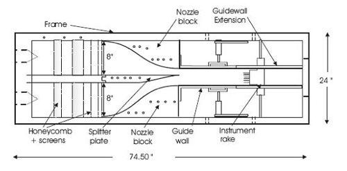
Fig. 1 Schematic of the S3L facility
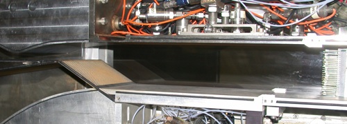
Fig. 2 Picture of the S3L test section outfitted with a Mach 2.5 nozzle on the top stream and the perforated expansion-ramp on the lower stream. The measurement rake is visible on the far right.
Flow in upper and lower streams
The top stream gas is supplied from a 1.2 m³ pressure vessel. Gas mixtures in this vessel are created using the partial pressure technique. The flow to the top stream is controlled with a servo-motor-actuated sonic valve. It can be operated in open-loop mode, set to deliver a constant mass to the upper stream, or with a proportional-integral-derivative (PID) control algorithm, set to deliver a constant pressure to the top stream. The stream is accelerated to the desired velocity through nozzles designed to minimize turbulence generation. Nozzles for M1 ≤ 1, 1.5 and 2.5 exist.
The flow to the lower stream is supplied from a Teflon bag within a smaller pressure vessel (0.57 m³). The Teflon bag is also filled with the desired gas mixture using the partial-pressure technique. During a run, the outside of the bag is pressurized with nitrogen from a 12.7 m³ surge tank, creating a very nearly constant supply pressure for the lower stream for the duration of a run without the need for active control. The bottom stream flow is metered using a calibrated sonic valve.
The shear layer
The facility can generate free-shear layers (Fig. 3) or re-attaching shear layers (Fig. 4), by injecting the lower stream gas near-parallel to the upper stream or through a perforated ramp at an angle to the upper stream, respectively.
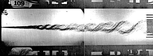
Fig. 3 Composite schlieren of the free shear layer, with the two streams injected parallel to each other. The upper stream is 100% N2 while the lower is a mixture of 1/3 He and 2/3 Ar, with M1 = 0.6.
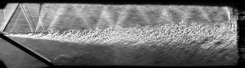
Fig. 4 Composite schlieren of the shear layer formed when the lower stream is injected through a 30° expansion ramp. The two streams are 100% N2, with the top stream at M1 = 1.02.
Fast chemical reactants
The facility is designed to handle fast-kinetic chemical reactants. Specifically, the top stream can be seeded with a mixture of hydrogen (H2) and nitric oxide (NO), and the bottom stream with fluorine (F2). The remainder of the gas in both streams is comprised of helium (He), argon (Ar) and nitrogen (N2) inert diluents, such that the desired ratio of density (molar mass) and specific (molar) heat capacities of the two streams can be set. Nitric oxide is added to the hydrogen stream to generate radicals on contact with fluorine to initiate the hydrogen-fluorine reaction. The reaction then proceeds hypergolically, obviating external ignition sources. Beyond the measurement rake, the flow expands to a large duct and is diverted into a chemically resistant catch bag. The products are then scrubbed down and neutralized using a NaOH solutions spray for subsequent release of any un-burnt reactants into the atmosphere.
Instrumentation and data acquisition
Pressure taps are included along the top and bottom guide walls, as well as the top and bottom stream plena. A measurement rake is located downstream of the tip of the splitter plate. The measurement rake consists of K-type thermocouples, static pressure probes, and total pressure probes. During a run, temperature and pressure data are recorded at 1 kHz/channel through a National Instruments LabView hardware/software data acquisition and control system.
The flow is visualized via high-speed schlieren photography. The schlieren setup employs a few-nanosecond duration light source (MiniStrobokin power supply with KL-L lamp) and a high-speed CMOS camera (Phantom v7.3). The schlieren setup is mounted on rails to allow imaging of both the forward and rearward portions of the test section.
Variable Pressure Flow (VPF) facility
GALCIT Free-Surface Water Tunnel (FSWT):
The planned-for Turbulent-Flow Visualization (TFV) facility:
Jet Flow Visualization (JFV) facility: